

Wastewater Treatment Blower Factory: Inside the Design and Production of Reliable Aeration Blowers
2026-08-26
Ask any plant operator what keeps a wastewater treatment line breathing, and the answer usually comes down to one unglamorous hero: the aeration blower. It runs in damp, corrosive air, often 24/7, and still has to deliver precise oxygen levels without draining the energy budget. This is the reality that shapes every design and production decision inside Seize Air's factory. Here's a closer look at how that demanding environment turns raw metal, motors, and engineering know-how into blowers built for the long haul.
Where Castings Meet CNC: The First Steps of Blower Assembly
The journey from raw casting to precision blower begins with a careful handoff. Fresh from the foundry, each housing and impeller carries subtle variations—slight shifts in wall thickness, tiny flashes along parting lines, or a faintly uneven bore. These aren't defects, just the honest fingerprints of molten metal cooling in a mold. On the bench, the first task is listening: tapping the casting with a small mallet to hear if the ring is clear and consistent, or muffled by an internal void. A dull thunk sends the part aside for deeper inspection, while a clean tone invites it forward.
Once the casting passes the ear test, the mating surfaces get a quick pass with a flat file and a machinist's straight edge. High spots from the sand mold are skimmed away, not to make the part pretty, but to give the CNC fixture a stable reference. If the datum pads rock on the table, every subsequent cut inherits that wobble. So we spend a few minutes with bluing and a scraper on the critical pads, chasing an even contact pattern. It feels old-school, but it saves hours of rework later when bores need to hold a couple thousandths.
With the casting seated true, the first CNC operations are deliberately light. A facing pass skims the mounting flange, revealing the metal's grain and any hidden porosity just beneath the skin. The impeller bore is roughed undersize, then measured with a dial bore gauge before the finish pass. This is where the casting's personality meets machine precision—feed and speed adjusted by feel for how the particular batch cuts. Some castings are buttery, others fight the tool. Learning that rhythm early means the blower assembly goes together without forcing, and the clearances stay where they belong when it spins up for the first time.
Balancing Act: Why Rotor Dynamics Decide Blower Lifespan
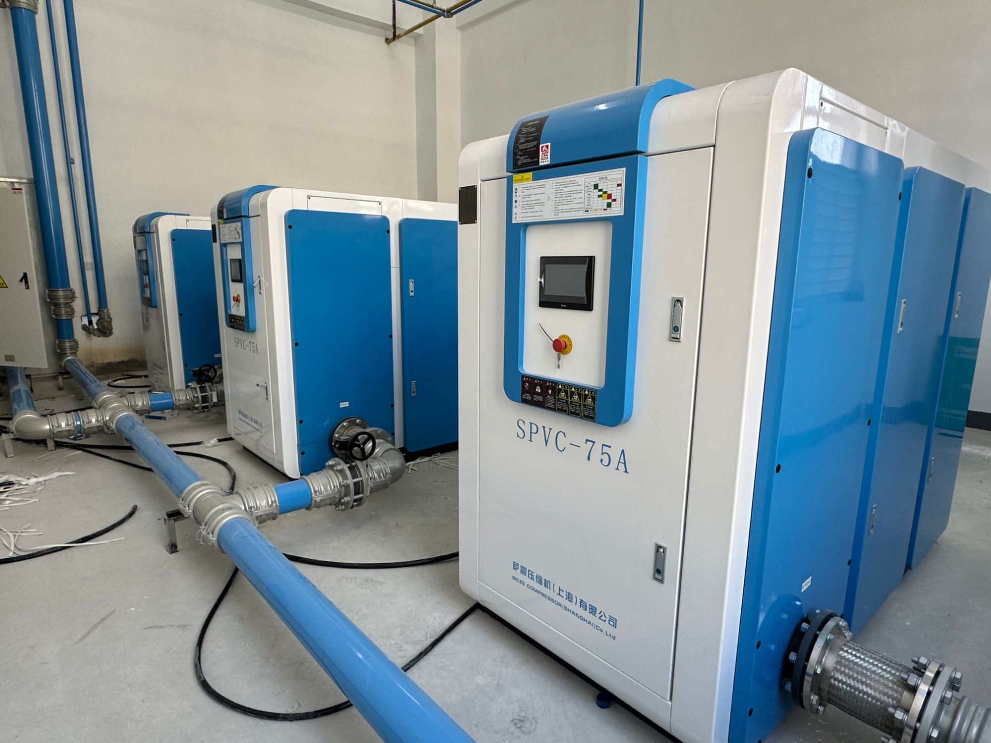
Every blower hums with an invisible argument between centrifugal force and structural fatigue. When the rotor is even slightly off-balance, that argument turns into a slow-motion hammering at the bearings. Most premature failures aren't caused by material flaws or lubrication gaps—they trace back to mass distribution across the rotating assembly. A few grams misplaced at speed generate forces that multiply exponentially with RPM, quietly eating away the safety margin designed into every component.
Think of rotor dynamics as the difference between a tightrope walker carrying a balanced pole and the same walker swinging a heavy bucket from one hand. The blower's shaft, bearings, and housing all feel that asymmetry. Over time, vibration creates micro-fractures in bearing races, fretting on mating surfaces, and loosening of fasteners. What starts as a barely noticeable hum becomes a destructive resonance that accelerates wear far beyond normal service intervals.
Field data from blower rebuilds consistently shows that units with precision-balanced rotors outlast their unbalanced counterparts by a factor of three or more. Balancing isn't a one-time event, though. Thermal growth, blade erosion, and debris accumulation shift the mass distribution during operation. Routine condition monitoring that tracks vibration signatures can catch these shifts before they become failures. In the end, the lifespan of a blower is written not in its horsepower or airflow rating, but in how well the rotating mass stays centered against the forces trying to pull it apart.
The Salt Spray Chamber and Other Tests We Never Skip
When a part fails after a few months outdoors, the salt spray chamber is usually the first suspect people point to. But in our experience, a standalone salt fog run rarely tells you the whole story. Real corrosion damage often comes from the way moisture, temperature swings, and chemical residues work together. That’s why we run the chamber in cycles rather than as a continuous fog, and why we pair it with a few other tests that catch what salt alone misses.
UV exposure is one of those tests. It seems unrelated until you see how a slightly degraded coating lets salt creep underneath. We also combine humidity soak and thermal shock, because the expansion and contraction from quick temperature changes can open microscopic gaps that a steady salt spray would never find. For components with seals or enclosures, a dust and water jet test comes next — not to check for corrosion directly, but to see whether the protective barriers survive long enough to matter.
None of this is glamorous, and the results don’t always line up with the datasheet. But skipping these tests only shifts the failure to the customer’s roof or deck. So we keep the chamber running, check the samples before they look obviously damaged, and log the small changes that most reports ignore.
Custom Impeller Design for Irregular Basin Layouts
Irregular basin layouts rarely line up with off-the-shelf impeller geometries. Corners, varying depths, and offset inlet positions create dead zones where standard radial or axial patterns underperform. Custom impeller design starts with mapping the actual flow path rather than assuming a symmetric vessel. Engineers often begin by measuring velocity profiles at several cross-sections, then iterating on blade curvature, pitch angle, and hub offset until the discharge sweeps the entire volume without excessive surface turbulence.
Beyond geometry, material selection plays a quiet but critical role. A basin with an odd footprint may demand an impeller that flexes under load or resists abrasion from settled solids. Some designs introduce variable blade lengths—shorter near tight walls, longer where open water allows. This uneven loading can be balanced by shifting the mounting point or adding a small secondary impeller. The goal is not just mixing but predictable turnover time even when the basin shape resists clean circular flow.
Testing remains indispensable. Computational fluid dynamics gets you close, but physical models in a scaled mock-up reveal nuances like vortex formation near angled walls. Field adjustments are common: a slight decrease in tip speed, a few degrees of blade twist, or even a trimmed shroud can flatten the velocity gradient. When done well, a custom impeller makes an irregular basin behave as if it were a standard round tank, without the cost of reshaping the structure itself.
Welding Stainless Steel for Corrosive Off-Gas Survival
Welding stainless steel for corrosive off-gas service rarely fails because of the base metal itself. It fails when the weld zone loses the very properties that made the alloy suitable in the first place. In acidic condensate or chloride-bearing exhaust streams, chromium carbide precipitation along grain boundaries can trigger intergranular attack within months. That is why filler metal selection matters more than most people admit. A 316L base welded with standard 316 filler may hold up in the lab but develop knife-line corrosion in the field. Matching low-carbon or stabilized grades—316L, 321, 347—and pairing them with the right consumables is the first line of defense, not an optional upgrade.
Back purging is another detail that separates a weld that survives from one that pits early. When the root side of a joint is exposed to oxygen during welding, it forms a dark, chromium-depleted oxide scale. In off-gas lines carrying sulfur compounds or halides, that rough scale becomes a starting point for crevice and pitting corrosion. Argon or argon-helium purging with a low oxygen reading below 20 ppm produces a smooth, silvery root that retains its passive layer. For duplex grades, the same care extends to interpass temperature control. Run too hot and you invite sigma or chi phase precipitation, which can embrittle the joint and reduce corrosion resistance even if the weld looks clean on the outside.
Post-weld treatment is not cosmetic in these environments. Pickling and passivation remove free iron and heat tint while helping the surface rebuild its chromium oxide film. But in streams with continuous condensation and aggressive halides, passivation alone may not be enough. Some systems require a barrier coating, a weld overlay with a higher alloy, or even anodic protection downstream. The most practical approach is to qualify the welding procedure under conditions that mimic actual off-gas chemistry, not just code minimums. Small changes in shielding gas, filler chemistry, or heat input often make the difference between a ductile, corrosion-resistant weld and a premature failure that no amount of coating can hide.
Matching Motors to Blowers Without Wasting a Single Watt
Selecting a motor for a blower often starts with a margin of safety that quietly turns into a permanent energy leak. Oversized motors run below their best efficiency range, drawing more current than the actual load demands and converting the excess into heat rather than useful airflow. The first step toward eliminating that waste is to measure the real operating point—static pressure and airflow—not the nameplate maximums. Once you know where the blower actually works, you can pick a motor whose efficiency curve peaks near that duty, not one that idles at 60 percent load.
Matching also means revisiting control strategy. A fixed-speed blower paired with a motor sized for worst-case conditions wastes watts during every normal hour. Using an electronically commutated motor or a variable frequency drive allows the system to follow the fan curve, trimming speed and input power as demand changes. The fan affinity laws make the stakes clear: reducing speed by 20 percent cuts power consumption by nearly half. That is not a theoretical ideal—it is a direct consequence of correct motor-blower pairing.
The payoff shows up in lower energy bills, cooler running temperatures, and longer insulation life, but only if the match is checked under actual duct conditions. A motor that saves watts on paper will still waste them if the blower housing, inlet restrictions, or filter loading differ from the design assumptions. Commissioning with a power meter closes that gap, verifying that the motor sits in its high-efficiency band while the blower delivers the required flow. When the measured watts align with the fan curve, the system is no longer guessing—it is using exactly the energy the process needs.
FAQ
Corrosion resistance starts with a cast iron or stainless steel casing paired with an epoxy coating, but the real work is in the air path. Inlet filters are oversized to keep moisture and particulates off the impeller, and shaft seals are specified for continuous exposure to hydrogen sulfide. That combination allows the blower to run for years without the housing degrading or losing volumetric efficiency.
Rather than assuming a fixed airflow, the design team works from the plant's diurnal load curve. They pair a positive displacement or high-speed turbo blower with a variable frequency drive, and then tune the control band so dissolved oxygen stays within a narrow setpoint. This avoids over-aerating at night while still meeting morning peaks.
Impellers are typically machined from aluminum alloy or stainless steel depending on the gas stream, and casings often use ductile iron with a two-part epoxy lining. Fasteners exposed to the wet well atmosphere are upgraded to 316 stainless, which prevents the kind of pitting that shortens the life of standard carbon steel units.
After an order is confirmed, the engineering team verifies the site's pressure and flow requirements, then releases drawings for laser cutting and CNC machining. Rotors are balanced individually before assembly, and each completed blower goes through a run-in cycle to seat bearings and check seal integrity. Only after passing that test does it move to final painting and crating.
Noise control is handled at the source rather than by adding bulky enclosures. The impeller profile and cut-off geometry are adjusted to reduce tonal peaks, and the base frame uses tuned isolators to stop vibration from reaching the pad. If a plant has strict residential noise limits, the factory can add a compact acoustic hood without changing the overall footprint.
Every unit is run on a test stand that simulates the actual back pressure of the aeration system. The factory logs airflow, discharge pressure, power draw, and bearing temperatures across several operating points. If a machine exceeds the vibration limit or shows a pressure pulsation outside the normal band, it is pulled from the line and reworked before shipping.
Yes, the control panel can be pre-wired for Modbus, Profibus, or Ethernet/IP, and pressure and temperature transmitters are installed at the factory. That gives the plant team a live view of blower health without needing to open the cabinet. Remote access also lets factory engineers assist with startup tuning rather than waiting for an on-site visit.
For emergency replacements, the factory keeps a stock of common frame sizes and impeller kits ready to assemble. A dedicated team can build, test, and ship a unit within a few days when a treatment plant is down. The goal is to match the existing piping and electrical connections so the replacement drops in without major civil work.
Conclusion
Inside a wastewater treatment blower factory, the journey from raw casting to dependable aeration equipment begins with a marriage of foundry work and precision CNC machining. Each impeller and housing starts as a rough casting that is then milled, drilled, and finished on multi-axis machines, ensuring the geometric accuracy that later determines how smoothly air moves through the system. Before any blower is cleared for assembly, rotor dynamics take center stage: every rotating assembly is dynamically balanced to tolerances far tighter than industry norms because even a few grams of imbalance can shorten bearing life and invite vibration-induced failures. This is not a step left to chance, and the balancing reports travel with each unit as part of its permanent record.
Beyond the machine shop, the factory runs a battery of tests that many suppliers quietly skip. Blowers destined for corrosive off-gas service are built with stainless steel housings and welds that have been qualified through salt spray chambers, cyclic humidity exposure, and pressure decay checks. For plants with irregular basin layouts or odd air demand curves, custom impeller designs—often trimmed or re-profiled after computational flow analysis—allow aeration grids to be fed evenly without dead zones. Finally, motor pairing is treated as an engineering exercise rather than an afterthought: drives are selected by mapping efficiency curves against actual operating points, so the blower consumes no more power than the process truly needs, year after year.
Contact Us
Contact Person: Mia
Email: [email protected]
Tel/WhatsApp: +86 19821985894
Website: https://www.seize-air.com