

ODM CNC Machining Guide for Engineers and Product Designers
2026-11-16
Every engineer knows the frustration of a perfectly rendered CAD model that falls apart in production. ODM CNC machining should bridge that gap, but too often the process remains opaque—filled with tolerance stack-ups, material quirks, and toolpath headaches. This guide from Tianyu strips away the guesswork, giving product designers a clear, practical path from prototype to high-quality manufacturing without the usual trial and error.
Material Selection That Survives Machining
A material that fights the cutter usually loses the battle in ways that show up later—microfractures, warped thin walls, or a surface finish that looks like torn grain. Free-machining alloys earn their reputation for a reason, but additives like lead or sulfur can quietly undercut corrosion resistance or weldability. The real trick is matching hardness to the operation: 6061-T6 aluminum cuts predictably if you manage chip evacuation, while 4140 pre-hardened steel asks for slower feeds but holds dimensions without drama. Skipping this step often means a beautiful CAD model becomes scrap after the second tool change.
Then there are plastics, where "survives machining" has less to do with tool life and more to do with not melting or shattering under the spindle. Acetal and PEEK tend to handle heat and cutting forces without grabbing the bit, while acrylic or thin polycarbonate can crack from internal stress alone. Even metal parts benefit from stress-relieving before finish passes—rolled plate and cold-drawn bar carry residual tension that releases mid-cut and bends a supposedly flat face. Choosing a material that's stable under the specific tool path, not just strong on paper, keeps the part from becoming a fixture-to-trash story.
Tolerances You Can Actually Hit
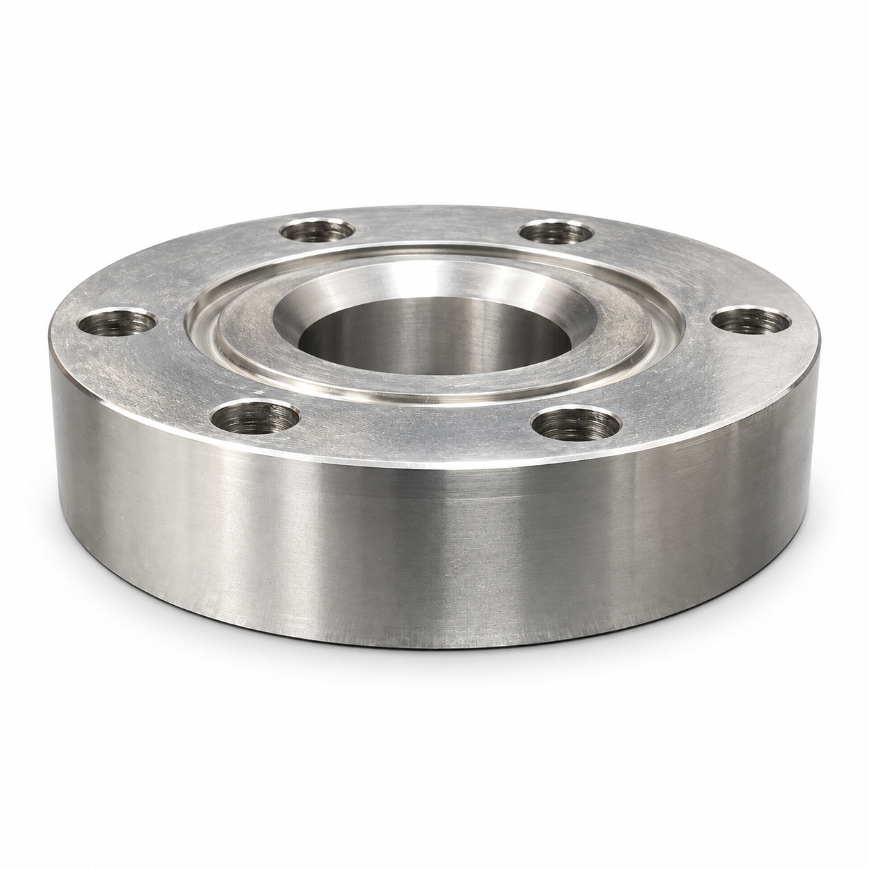
Most drawings list tolerances that look reasonable on paper, but the moment you clamp the part and start cutting, reality gets more complicated. The tolerance you can actually hold depends on machine condition, tool wear, and how consistently you measure—not just the resolution of the readout. Experienced machinists often rely on sound, chip shape, and feel to know whether a cut is still within range.
For typical milling and turning work, ±0.005 inches rarely demands special effort. But once you move inside ±0.001 inches, thermal expansion, clamping distortion, and even temperature swings between morning and evening start to matter. The answer isn't always a more expensive machine; it's finding a stable clamping point and a repeatable datum on each workpiece.
Instead of trusting the extreme limits in a brochure, run a small test batch on your own equipment and record the actual deviation spread. That gives you a tolerance you can genuinely quote and hold, rather than one that only works in ideal conditions.
Finishes That Don't Fight the Toolpaths
A finish should work with the geometry left by the cutter, not against it. Brushed or lightly blasted surfaces tend to follow the natural sweep of a toolpath, letting subtle scallops read as texture instead of defects. Glossy clear coats, by contrast, magnify every stepover line and make even tight tolerances look sloppy.
When choosing a coating, think about how light hits the machined face. Matte and satin anodizing or thin powder coats mute high spots and blend tool marks into a consistent haze. They don't hide the machining; they give it a deliberate, functional backdrop that keeps the focus on form and fit.
The goal isn't to erase evidence of the process. It's to pick a finish that doesn't require sanding away the very marks that prove the part was cut cleanly. That approach saves time, preserves dimensional accuracy, and leaves a surface that feels intentional rather than overworked.
Cost Drivers Hidden in Your CAD File
Every CAD file carries more than geometry—it carries decisions. A seemingly innocent fillet, an unnoticed thread specification, or a tolerance tighter than the process can hold will quietly inflate your quote. These aren't errors; they're embedded assumptions that most designers never revisit. When a machinist sees a 0.005 mm true position on a hole that only locates a cosmetic cover, they see extra setups, optical inspection, and scrap risk. And that's before anyone mentions the custom surface finish specified on a non-functional face.
Material selection often hides the biggest cost leaks. A generic “6061-T6” might sound cheap, but if the part has thin walls or deep pockets, the same alloy could require slow roughing passes and specialized workholding just to avoid distortion. Meanwhile, a near-net shape in 7075 or even a switch to a free-machining brass could cut cycle time by 40%. The CAD file won't tell you this—it just sits there, looking innocent. You have to interrogate the features: Why is this pocket square-cornered? Does this boss really need a 16 microinch finish? Every yes that isn't justified is a cost driver hiding in plain sight.
Part complexity also scales non-linearly. Five simple holes cost five times one hole. But five holes with three different diameters, two thread pitches, and a counterbore? That's not five operations—that's a tool change marathon, maybe a second setup, and a higher chance of human error. Your CAD file won't show the tool turret filling up, but it's right there in the feature tree. The trick is to read your own design like a cost accountant: merge, standardize, and ask if that pocket really needs a 3 mm internal radius or if 6 mm would do. Often, the cheapest change is the one you make before the file ever leaves your desktop.
From Prototype to Production Without Redesign
Many teams treat the prototype as a throwaway sketch, only to discover that the path to a real product demands a complete architectural overhaul. The smarter approach is to build the prototype on the same foundations you intend to ship: the same data models, the same state management, the same deployment pipeline. That doesn't mean over-engineering every experiment, but it does mean making deliberate choices about where flexibility ends and production readiness begins.
A common failure is separating the prototype’s logic from the eventual system’s constraints. For example, if your prototype stores everything in memory and ignores authentication, moving to a persistent multi-user environment will force you to rewrite not just the storage layer, but also the UI flows that assumed a single session. Instead, choose boring, proven components early—a relational database, a standard REST or GraphQL layer, basic role checks—so the prototype can be hardened incrementally rather than replaced.
The real art is designing for evolution without paying the full cost of production from day one. You can use feature flags to hide unfinished admin tools, keep observability lightweight at first, and write integration tests only for the few critical paths. This way, the same codebase grows from a rough demo into a stable service, and you never face the demoralizing moment of telling stakeholders that everything must be rebuilt from scratch.
Design Mistakes That Break End Mills
Most tool failures get blamed on speeds and feeds, but a surprising number of broken end mills trace back to decisions made before the cutter ever touches metal. A tapered core that gets too thin near the flute roots, for example, leaves the tool vulnerable to snap under heavy radial loads. Sharp internal corners where the flute meets the shank create stress risers that turn normal vibration into fatigue cracks. These geometry choices seem minor on a drawing, yet they dictate how force travels through the carbide.
Another recurring mistake is designing for chip evacuation without thinking about rigidity. Deep, polished flutes may clear aluminum beautifully, but that removed material weakens the cross-section exactly where bending stress peaks. In harder steels, the same design leads to sudden breakage instead of gradual wear. Adding a slight corner radius or adjusting the rake angle can shift the failure mode from catastrophic fracture to predictable flank wear, giving machinists a chance to swap the tool before it fails.
FAQ
One common miss is internal corner radii. Designers sometimes leave sharp internal corners, but CNC tools are round, so a sharp corner forces either a tiny tool with long cycle time or a secondary EDM step. Always specify a radius that matches a standard end mill, like 3 mm or more, to keep machining economical. Another overlooked area is wall thickness—too thin and the part vibrates during cutting, causing poor finish and tolerance drift.
Think about what the part actually needs. 6061 machines cleanly, welds well, and resists corrosion, which makes it a solid default for housings, brackets, and general-purpose parts. 7075 is stronger and harder, closer to mild steel in strength, but it's more expensive and trickier to anodize consistently. Use 7075 only when you need that extra strength-to-weight ratio, like in aerospace or high-stress fixtures, otherwise 6061 will save money and headaches.
As-machined finish is the baseline—usually fine for internal surfaces but shows visible tool marks. Bead blasting knocks down those marks and gives a uniform matte look, though it can slightly round sharp edges. Anodizing adds a hard oxide layer that improves wear and corrosion resistance, but it changes dimensions by a few microns, so you need to account for that in tight fits. Powder coating is thicker and hides machining lines completely, but avoid it on mating surfaces unless you mask them.
Use 5-axis when the part has features on multiple non-orthogonal faces, like angled holes or compound curves, because it lets you reach those in a single setup. That reduces fixture changes and alignment errors, which matters for parts with tight positional tolerances across different planes. For simple prismatic parts, 3-axis is still faster and cheaper, so don't pay for 5-axis just because it sounds advanced.
Start by reducing material removal—deep pockets and large flat areas with tight flatness eat up machine time. Design with standard stock sizes in mind and avoid unnecessary tight tolerances on non-critical features. Keep tool access straightforward: if a feature needs a long reach or a right-angle head, cost jumps. Also, batch similar parts together to share setup time, and use tapped holes sparingly because thread milling is slower than drilling a clearance hole.
A well-maintained CNC mill can hold ±0.05 mm on features like holes and bosses without much effort. Tighter than ±0.025 mm usually requires careful tool selection, slower feeds, and possibly temperature-controlled environments. Only specify those tight tolerances on mating or alignment features, like bearing bores or dowel pin holes. Every decimal place you add to a tolerance drives up cost and inspection time.
CNC machining is subtractive, so you're fighting tool access, vibration, and material removal rates—deep pockets, thin floors, and internal undercuts are pain points. Injection molding is about flow, cooling, and ejection: you need draft angles, uniform wall thickness, and no trapped undercuts. In CNC, you can have variable wall thickness without penalty, but sharp internal corners are a problem. In molding, sharp external corners are fine, but internal ribs need careful sizing to avoid sink marks.
Check functional fit first—mating parts should assemble without force. Measure critical dimensions with a CMM or micrometer, especially hole positions and flatness on sealing surfaces. Run the part through its actual load case if possible, because CNC prototypes can hide stress risers from sharp corners or thin sections. Also, test the surface finish in real conditions, like checking an anodized part for wear after repeated cycles. If the material and tolerances match production intent, you can usually skip additional DFM changes.
Conclusion
A reliable ODM machining workflow starts before any tool touches metal. Material choice isn't just about strength or cost—it's about whether the alloy will warp, gum up, or chatter under real cutting loads. Engineers who skip this step end up chasing tolerances they can't hold. Speaking of tolerances, the numbers on a drawing often assume ideal conditions that a job shop can't recreate. Tighten only the features that matter, and give the machinist room to hit the rest without constant probing. Finish calls matter too: a mirror polish on a deep pocket can fight the toolpath and double cycle time, while a simple bead blast often hides tool marks and improves grip. Most of the real cost is locked in before quoting, buried in CAD geometry—sharp internal corners, deep thin walls, or unnecessary threads that force extra setups.
The jump from prototype to production doesn't have to mean a full redesign if the first version respected machining limits. Keep radii standard, avoid undercuts that demand custom fixtures, and leave room for tool deflection. Common failures—snapped end mills, burned inserts, scrapped parts—usually trace back to a few avoidable choices: a slot too narrow for chip evacuation, a pocket too deep for the reach, or a material too hard for the speeds assumed. Designers who learn to read toolpaths as physical cuts, not just screen geometry, will find that suppliers quote faster, scrap less, and hit delivery dates without drama. The guide's core message is simple: machining-friendly design isn't a constraint; it's the cheapest form of manufacturing insurance you can add before money is spent.
Contact Us
Contact Person: Vera Yao
Email: [email protected]
Tel/WhatsApp: 8618512832770
Website: https://www.tianyucnc.com