

China M12 Connector Selection Tips for Reliable Industrial Connectivity
2026-11-16
Most industrial network failures don't start with a broken cable—they start with the wrong M12 connector. In China's crowded component market, identical-looking parts can behave very differently under vibration, moisture, and temperature swings. This guide cuts through the noise with practical selection tips for reliable connectivity, drawing on REUNION's field experience.
The Mating Cycle Rating Your M12 Actually Needs
Most M12 connectors carry a mating cycle rating that gets repeated on datasheets without much thought. The number—often 100, 500, or more—sounds reassuring, but it rarely reflects what a specific installation will experience. A sensor block inside a guarded cell might be unplugged twice a year for cleaning, while a mobile robot charging dock could see the same connector coupled and uncoupled every shift. The rating your M12 actually needs hinges on that mechanical rhythm, not on a generic benchmark.
Start by counting the real plug/unplug events across the expected service life. If the connector lives in a fixed harness and only gets disconnected during major overhauls, a modest cycle rating is enough and chasing a higher figure adds cost without adding function. On the other hand, applications with frequent tool changes, cable swaps, or portable equipment need headroom because wear on contacts and locking threads accumulates faster than the datasheet suggests.
It also helps to separate electrical wear from mechanical wear. A connector might still latch after hundreds of cycles but show increased contact resistance long before that. If your M12 carries low-level analog signals, a degraded contact matters far sooner than it would in a 24 V digital circuit. Matching the mating cycle rating to how often the connector actually moves—and what it carries when connected—keeps the spec honest.
Why A-Coded M12s Are Not Interchangeable With D-Coded
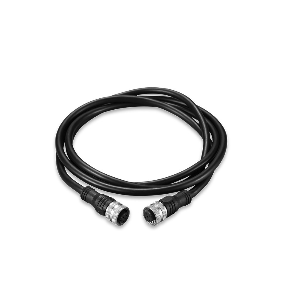
The M12 connector family uses different keying patterns precisely so that connectors with different signal functions cannot be accidentally mated. In an A-coded M12, the inner sleeve and pin layout are arranged for sensor, actuator, and low-voltage DC applications, typically carrying 24 V power, discrete I/O, or analog signals. A D-coded M12 has its keyway rotated to a different position and is built around a four-pin data layout intended for industrial Ethernet. That difference in physical orientation means an A-coded plug will not seat correctly in a D-coded socket, and forcing the connection is almost always a sign that the wrong cable or port is being used.
Even if the two connectors could be forced together, the internal wiring would still create problems. D-coded cables are manufactured with twisted pairs and controlled impedance to support 100 Mbps protocols such as PROFINET or EtherNet/IP. A-coded cables are usually not constructed to the same transmission standards, so using one in place of a D-coded link can cause packet loss, link drops, or complete network failure. Going the other direction is just as risky because a D-coded cable is not designed to handle the power levels or the mixed signal assignments commonly found on A-coded runs, which can lead to unreliable sensor operation or damage to connected equipment.
Plating Choices That Hold Up When Vibration Never Lets Up
When vibration is constant, the real failure point often isn't the connector or the component itself—it's the plating that quietly wears away under micro-motion. Standard gold over nickel works fine on a stable bench, but out in the field, repeated fretting scrapes through thin layers and exposes base metal. The result is intermittent contact, rising resistance, and a fault that only shows up after hours of runtime.
A better route is to match the plating stack to the actual movement pattern. Hard gold with a heavier nickel underlayer holds up longer against sliding wear, while palladium-nickel alloys offer a tougher surface for high-cycle insertion. For tin-plated terminals, thicker tin doesn't always help—what matters more is reducing relative motion through better connector locking and adding a lubricant that stays put under vibration.
The most reliable designs don't rely on one miracle coating. They combine a wear-resistant top layer with a forgiving underlayer and a mechanical design that limits fretting amplitude in the first place. That combination is what keeps resistance stable when the whole assembly is shaking nonstop.
The Difference Between IP67 on Paper and IP67 Under Coolant
An IP67 rating is earned in a lab, not on a shop floor. The standard test means a device gets lowered into still tap water for thirty minutes at a depth of one meter. That is a clean, static, room-temperature dunk. Coolant is a different animal: it contains emulsifiers, tramp oil, fine metal particles, and biocides that attack O-rings, cable jackets, and potting compounds. Because the surface tension is lower than water, coolant slips into capillary gaps that clean water would simply bridge over. A connector that passes the paper test can still wick fluid once it is hit by a warm spray at a tool change.
Temperature cycling is the part the rating never captures. In a machine, a housing warms up while the spindle runs and cools after shutdown. That breathing cycle pulls moist air inward and pushes it out again. If a cable gland or vent is not built for that negative pressure, coolant gets drawn past a seal that was only tested under static conditions. The failure does not require immersion. Condensation alone is enough to fog a lens or start corrosion on a pin.
So IP67 is best treated as a starting point, not a survival guarantee. The practical test is how the component holds up in a specific sump, with its own coolant concentration, temperature swings, and splash direction. Some failures are slow, with fluid creeping along a cable jacket until it finds a low spot. Others happen after a single washdown. The paper rating tells you it can hold back standing water; it says little about living in coolant.
What to Ask a Chinese Connector Supplier Before Bulk Orders
Before you wire a deposit, get the supplier to walk you through the actual approvals file for the exact series you are buying. Ask whether the UL file number covers your terminal pitch and housing configuration, not just a similar part. Request the full plating spec: base material thickness, underplate, and finish plating, including whether it is tin over nickel or selective gold, and what salt spray or porosity testing they have run on recent batches. If they hesitate on test dates or test reports, that is a red flag because Chinese connector factories often share generic data sheets across multiple customers.
Dig into tooling and lot control rather than just unit price. Find out who owns the mold, how many cavities it runs, and what the current cavity condition is when your order will be produced. Ask how they handle dimensional drift across long runs and whether they will provide actual Cpk data for critical dimensions like contact retention and insertion force. Also pin down the change management rule: if they swap resin suppliers, adjust plating thickness, or move production to another floor, you should know before containers ship, not after.
Pricing and lead time should be tied to concrete assumptions. Ask what happens to lead time if material supply slips or export inspection finds a batch problem, and confirm the factory holds enough raw material on hand for your first two reorders, not just the initial PO. Ask for a clear quality rejection process: who pays return freight, how quickly replacements ship, and whether credit notes are issued without a long dispute. These operational details reveal whether the supplier can carry a long-term relationship, not just a one-off quote.
Field Failures That Trace Back to Weak Cable Strain Relief
A significant share of field returns never make it past the bench diagnosis stage at first glance. The connector looks seated, the cable jacket shows no obvious cuts, and the device passes a quick continuity check. Weeks later, the same unit comes back with an intermittent power fault. The culprit is often hidden inside the grip area where the cable meets the housing. Repeated bending, tugging, or even routine handling creates micro-fractures in the conductors just beyond the solder joints, while the outer jacket stays intact. Because the strain relief was treated as an afterthought, it never limited the bend radius at that critical transition point.
What makes these failures costly is the delay between cause and symptom. A weak strain relief can hold up long enough to survive final inspection and initial installation, then degrade once the equipment is in real use. Vibration, temperature swings, and maintenance pulls gradually work the conductors loose or crack the insulation. By the time the device misbehaves, it is no longer a simple assembly error; it is a reputation problem. Field technicians start replacing whole cable assemblies instead of trusting individual connections, and support tickets rise for issues that lab testing never reproduced under static conditions.
The fix rarely demands exotic materials. It starts with recognizing the strain relief as part of the electrical path, not just a cosmetic boot. Molded tapers, internal clamping, and adequate clearance behind the termination all help move mechanical stress away from the most fragile points. Prototype validation should include repeated flexing at the housing exit, off-axis pulling, and cold-bend checks before the design is released. If those tests are not performed early, the field will eventually perform them in the worst possible environment.
FAQ
A-coded is the workhorse for sensors, actuators, and most 24V DC signal work. If you are mixing Ethernet or higher-speed data on the same floor, that is where X-coded or D-coded becomes necessary, not just a nice upgrade.
Look beyond the plastic shell. A reliable choice usually has a threaded metal coupling with proper torque, gold-plated contacts, and an internal strain relief that keeps cable movement away from the solder or crimp points. Cheaper units often skip the strain relief details.
Ask for actual third-party test reports for IP67/IP69K or salt spray, plus samples for pull and continuity testing. Consistency matters more than a glossy datasheet, so order a small batch first and inspect plating, thread finish, and pin alignment under magnification.
Only if the connector provides a continuous 360-degree shield path to the housing and your system has a proper ground reference. A shielded cable terminated into a plastic connector with no drain connection adds cost and can make noise problems harder to trace.
Confirm the housing material and seal material match the cleaning agents. Stainless steel or high-grade nickel-plated brass holds up better than zinc alloy in acidic washdowns, and FKM seals often outlast nitrile when sanitizers are used.
Pin count alone is not a spec. Contact resistance, plating thickness, insulator material, and shell design all vary widely. One may use 0.8 micron gold over nickel while another uses flash gold that wears off after a few mating cycles.
For repairs and custom cable lengths, yes, if installers are trained and use the right torque. For high-volume production, molded cable assemblies are usually more consistent because they eliminate termination errors and seal assembly mistakes.
Conclusion
Sorting through M12 connectors for industrial use means looking past the basic sales sheet, especially when sourcing from China. Start with mating cycles: a connector rated for 500 cycles may be overkill on a fixed sensor block but inadequate on a robot wrist that gets unplugged during every shift change. Coded variants trip people up because an A-coded and a D-coded M12 can share the same shell yet carry completely different signals. Using an A-coded unit in a D-coded Ethernet line often shows no visible damage while causing intermittent data faults, so pin maps and impedance need to be checked before ordering. Plating is another silent factor. In high-vibration areas, thin gold flash over nickel wears quickly and invites fretting corrosion; a heavier gold layer on the contact points, with proper underplating, holds up much better.
An IP67 rating also deserves closer scrutiny. It proves survival in a short static dunk, but coolant spray, thermal swings, and oil mist push seals harder in real life. Ask what elastomer is used and whether the supplier has tested against the specific fluids on your floor, not just clean water. Before committing to a bulk order, request batch samples with plating thickness, mating cycle reports, and the actual crimp dimensions they will use. Many field failures never originate in the contact itself; they start at the cable entry where weak strain relief lets conductors flex until they break. A molded or properly clamped strain relief matched to the cable jacket diameter, sometimes with an added metal sleeve, prevents those intermittent open circuits that are expensive to chase later.
Contact Us
Contact Person: Hayley Liang
Email: [email protected]
Tel/WhatsApp: +86 13480625451
Website: https://www.reunion-china.com/