

Best Purification Panel Production Line Essentials for Consistent Air Quality Control
2026-11-18
Air quality control seldom grabs attention until something drifts out of spec. Yet in cleanrooms, coating lines, and precision welding environments, the real differentiator isn't the filter you replace—it's the purification panel production line behind it. That’s where dimensional consistency, sealing integrity, and airflow uniformity are won or lost long before a panel reaches your facility. At YI ZHOU TECHNOLOGY, we’ve watched too many teams chase symptoms while the root cause sat upstream in fabrication. This guide breaks down the essentials that separate a reliable line from one that quietly undermines your air quality goals.
Raw Media Conditioning Before It Touches the Line
Conditioning raw media isn't a preliminary step to rush. Rolls of film, paper, or foil often arrive at different core temperatures and moisture levels, and unloading them straight into a press or converting line invites registration drift, static buildup, and uneven coating. Letting the stock acclimate in the same environment as the production floor—usually 12 to 24 hours depending on caliper and wrap—gives the material a chance to settle before tension and heat start pulling at it.
Beyond temperature and humidity, surface preparation matters just as much. A quick pass with an antistatic bar or a tack cloth removes the fine dust that causes fisheyes and voids once coating or lamination begins. Some operators also run a low-tension web cleaner right at the unwind stand, catching loose fibers before they get trapped between layers. The goal is to present the line with a clean, stable substrate rather than asking downstream controls to correct for problems that started at the dock.
Getting this phase consistent means documenting what “ready” actually looks like for each material. A polypropylene film might need only a short rest and static neutralization, while a heavy board stock could require extra time to equalize and a splice table check for edge nicks. Small adjustments at this stage usually cost minutes; the defects they prevent tend to cost hours once the material is running.
Precision Pleating That Keeps Airflow Resistance Steady
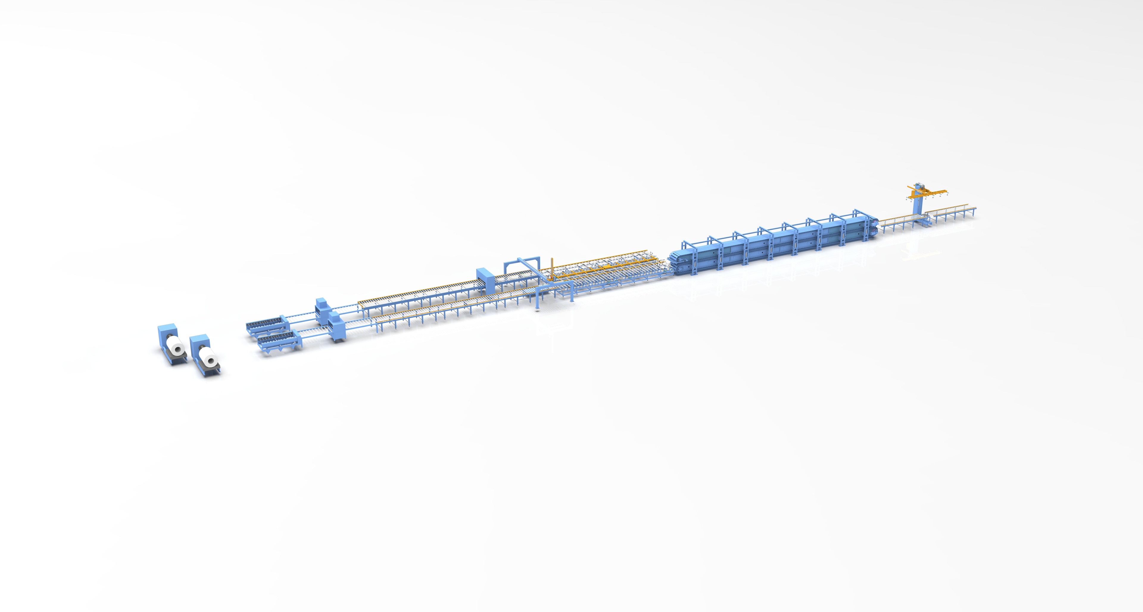
The pleat geometry here isn't just for show. Each fold is set at a controlled depth and spacing so the media doesn't bunch up or collapse under load. That means as dust builds on the surface, the open channels between pleats keep doing their job instead of pinching shut and choking the system. The result is a resistance curve that climbs slowly and predictably, not one that spikes the moment the filter sees a little real-world dirt.
You'll notice the difference most on longer service intervals. With many filters, the first few hundred hours feel fine, then airflow drops off a cliff. Here the pleat support stays uniform from edge to edge, so the face velocity doesn't creep up in random hot spots. Fewer pressure swings mean the fan doesn't have to work harder over time, which quietly extends the life of the whole air handling setup.
What really sets this apart is how the pleats are locked in place. A stiffened separator pattern holds each fold in registration, even when wet or exposed to high humidity. That prevents the classic sag-and-touch failure where adjacent pleats lean into each other and block half the media area. Steady resistance isn't a marketing claim—it's a structural outcome of the way the pack is built.
Adhesive and Seal Discipline at Every Joint
Most envelope failures never start in the middle of a wall. They begin at the intersection where two materials meet, a window buck against sheathing, a roofline transition, an expansion joint that moves more than the drawings suggested. Treating these lines as afterthoughts is what turns a minor capillary leak into rot, mold, and costly rework.
The sequence matters just as much as the product. A bead laid over dust, frost, or damp substrate might look complete in the afternoon but will peel away by the first seasonal cycle. Clean cuts, backer rod placement, correct depth-to-width ratios, and tooling the sealant into contact with both faces are the quiet details that separate a building that stays dry from one that quietly absorbs water for years.
Consistency also means reading the joint for what it actually does. A static seam in a conditioned interior needs a different approach than a high-movement facade joint facing ultraviolet and driven rain. Matching the sealant's movement capability, cure type, and adhesion profile to the real stress on that line, and repeating the same standard at every floor, is what keeps the entire assembly predictable.
Inline Leak Testing Without Letting Bad Panels Slip Through
A reliable inline leak test does more than flag gross failures; it catches the subtle porosity and micro-cracks that visual checks miss. On a fast-moving panel line, the difference between a pass and a quiet reject often comes down to how well the test station isolates each cavity and reads pressure decay under real cycle times. Shortening the test without sacrificing sensitivity means paying attention to fill stabilization, sensor placement, and clamping force, not just the leak rate threshold.
Bad panels slip through when the process relies on spot checks or when operators override borderline results to keep output moving. Inline systems remove that temptation by making every panel face the same measurement, with pass/fail locked to the actual leak signature. The key is setting limits that track the production baseline and drift, so a deteriorating seal or worn fixture shows up before it creates a batch of escapes.
It helps to treat leak testing as part of the panel's manufacturing story rather than a final gate. Data from each test can reveal which upstream operations are introducing variation, whether it is a weld sequence, adhesive application, or material batch. When that feedback loop is short, the line stops producing suspect panels instead of simply sorting them afterwards.
Calibration Frequencies Tied to Real Run Data
Calibration schedules rarely survive contact with actual usage patterns. Instead of setting an arbitrary annual or quarterly reminder, the interval can shift based on how often a device is used, under what loads, and how far its readings drift between checks. A sensor that logs heavy daily cycles in a dusty environment may need attention long before a unit that sits idle most weeks.
Pulling in real run data makes this more concrete. Runtime hours, cycle counts, temperature swings, and historical as-found versus as-left results can all feed into a frequency model. When past calibrations show a consistent drift trend, the next date tightens up. If several rounds come back within tolerance, the window relaxes without compromising certainty. This keeps maintenance effort focused where it actually reduces measurement risk.
The result is a system that feels less like a fixed checklist and more like a feedback loop. Teams stop calibrating on paper and start responding to how instruments behave in service. That shift tends to cut unnecessary work while catching the units most likely to drift.
End-of-Line Handling That Preserves Rated Performance
The moments after a product leaves the main process are often where throughput quietly erodes. A filler, capper, or cartoner may hold its rated speed without difficulty, yet the line still misses target because the end-of-line equipment fights the flow. Keeping that rated performance intact means treating palletizing, case handling, and stretch wrapping not as downstream afterthoughts but as synchronized parts of the same rhythm. Buffer zones, gentle accumulation, and timed release prevent backpressure from reaching the primary machine, so a brief downstream pause never becomes a reason to slow the entire line.
Sustaining speed also depends on how transfers and directional changes are executed. Servo-driven diverters, low-friction conveyor transitions, and tooling that matches the product footprint reduce the micro-stops that accumulate into lost cases per shift. On palletizers, layer forming should overlap with the next row arriving rather than waiting for a clean stop. Wrapping and labeling stations are configured to cycle faster than the upstream discharge rate, giving the system enough headroom to absorb variation without falling behind. That headroom is what protects the line's rated output when a flap folds out of place or a pallet exchange takes a second longer than expected.
The real proof is not a short demonstration run, but sustained behavior across a full production window. When end-of-line handling preserves rated performance, operators notice fewer manual interventions, more consistent pallet quality, and fewer alarms caused by product jams. Electrical and pneumatic loads stay within design limits because the line is not constantly catching up from a deficit. Over time, that translates into predictable shift counts, stable energy draw, and less wear on drives and actuators—evidence that the end of the line is contributing to output instead of quietly limiting it.
FAQ
A visible frame dent is caught before shipping, but a thin void in the seal lets unfiltered air slip past under pressure. Over time the leak channel widens with vibration and thermal cycling, so panels that tested clean on day one can become the main source of particle carryover.
At the point just after adhesive is applied and before the media enters the curing tunnel. If spacing drifts there, the pleats set unevenly and later corrections only mask the problem. Operators should check edge-to-edge spacing, not just the middle, because edges tend to open first.
A burst or leak test after full assembly, run at a pressure just above the panel's rated operating range. Lab samples can be hand-fitted, but production panels need to prove the seal and media survive the same stress they will see when the system ramps up.
Fiber orientation and basis weight shift slightly between lots, and those small changes alter how the pleats open during curing. A line that relies only on final pressure drop will chase the variation downstream; a better approach is to log lot numbers with resistance readings so adjustments trace back to the material.
When adhesive temperature or cure time starts drifting outside the narrow window the panel design assumes. Running faster saves minutes but produces panels that may delaminate at the corners later. Slowing the line returns the process to a stable thermal profile and protects consistency more than extra volume does.
By checking diagonal measurements on a sample of frames every shift, not just at startup. A warp of even a few millimeters may still assemble correctly but will sit poorly against the housing gasket. Catching the trend early is cheaper than replacing a full pallet of finished panels.
The first panel reflects the line's cold-start condition, including adhesive viscosity and pleater tension. If that value is treated as the baseline, later warm-line readings look artificially stable. Tracking the first panel separately reveals whether startup settings need adjustment before they affect the rest of the batch.
It controls the three variables that degrade on a shift: seal depth, pleat height, and cure temperature. When those remain within tight bands, the finished panels behave like the approved sample. Without that control, every successful lab test becomes a one-off event rather than a reliable output.
Conclusion
A dependable purification panel line rarely begins with the pleater itself. Raw media has to be conditioned before it reaches the first forming station, because variations in moisture, tension, or surface distortion show up later as unstable airflow resistance. Once the material is stable, precision pleating matters less for appearance than for repeatability: consistent pleat height and spacing keep pressure drop within a narrow band, which is what actually protects downstream air quality. Adhesive and seal discipline gets less attention but causes many field failures. Every joint needs a controlled bead, enough open time, and proper compression so the panel does not bypass air at the edges.
Inline leak testing should be treated as a gate, not a sampling exercise. Testing every panel with a consistent pressure or aerosol challenge catches defects before they leave the line, rather than relying on later audits. Calibration frequencies should follow real run data instead of a fixed calendar: shifts, batch changes, and drift trends often reveal when instruments need adjustment before they produce bad readings. End-of-line handling also deserves strict controls, since crushed corners, compressed media, or broken seals can erase the performance built earlier. In practice, the line performs well only when these stages are managed as one continuous system, with measurements and process limits supporting each other.
Contact Us
Contact Person: Sophia Jiang
Email: [email protected]
Tel/WhatsApp: +86 17367381818
Website: https://yzwelding.com/